- Yamaha fjr 1300 руководство по ремонту
- Каталог файлов
- Yamaha fjr 1300 руководство по ремонту
- Каталог файлов
- Руководства по эксплуатации, обслуживанию и ремонту мотоциклов Yamaha серии FJR
- Руководство пользователя Yamaha FJR1300AS.
- Owner`s Manual Yamaha FJR13.
- Owner`s Manual Yamaha FJR1300.
- Yamaha 2001 FJR1300(N) Service Manual.
- Yamaha 2006 FJR1300A(V) Service Manual.
- Yamaha 2004 FJR1300(S)/FRJ1300A(S) Supplementary Service Manual.
- Yamaha Motorcycles Service Manual 2005.
- Скидки от справочной
- Обзор мотоцикла Yamaha FJR 1300
- Yamaha FJR1300 2001, FJR1300(N) (2001) Service Manual
- TABLE OF CONTENTS
- GENERAL INFORMATION
- FEATURES
- FI SYSTEM
Yamaha fjr 1300 руководство по ремонту
Понедельник, 05.07.2021, 15:00
- Главная страница
- Технические характеристики
- Сравнение моделей FJR
- Каталог файлов
- Каталог статей
- Каталог сайтов
- Форум
- Фотоальбом
- Доска объявлений
- FAQ (вопрос/ответ)
- Гостевая книга
- FAQ (по FJR1300 01-08)
Лучшие фотографии:
Сегодня на форуме:
Барахолка:
| Категории каталога | ||
|
| Форма входа | |||
Каталог файлов
Разные мануалы и рукаводства для FJR разных годов. Источник Yamaha fjr 1300 руководство по ремонтуПонедельник, 05.07.2021, 15:00
Лучшие фотографии: |
| Категории каталога | ||
|
| Форма входа | ||
Каталог файлов
Сортировать по: Дате · Названию · Рейтингу · Комментариям · Загрузкам · Просмотрам Разные мануалы и рукаводства для FJR разных годов. Источник Руководства по эксплуатации, обслуживанию и ремонту мотоциклов Yamaha серии FJRРуководство по эксплуатации и техническому обслуживанию мотоциклов Yamaha FJR1300A.
Руководство пользователя Yamaha FJR1300AS.Руководство по эксплуатации и техническому обслуживанию мотоциклов Yamaha FJR1300AS.
Owner`s Manual Yamaha FJR13.Сборник руководств на английском языке по эксплуатации и техническому обслуживанию мотоциклов Yamaha моделей FJR13AD(C)/AEV(C)/AEY(C)/AV(C)/AX(C)/AZ(C).
Owner`s Manual Yamaha FJR1300.Сборник руководств на английском языке по эксплуатации и техническому обслуживанию мотоциклов Yamaha моделей FJR1300/A/AP/AS(C)/AT(C)/N/R/RC/S(C)/T(C).
Yamaha 2001 FJR1300(N) Service Manual.Руководство на английском языке по ремонту мотоциклов Yamaha моделей FJR1300 и FJR1300N 2001 года выпуска.
Yamaha 2006 FJR1300A(V) Service Manual.Руководство на английском языке по ремонту мотоциклов Yamaha моделей FJR1300A и FJR1300AV 2006 года выпуска.
Yamaha 2004 FJR1300(S)/FRJ1300A(S) Supplementary Service Manual.Руководство (дополнение) на английском языке по ремонту мотоциклов Yamaha моделей FJR1300, FJR1300A, FRJ1300AS и FRJ1300S 2004 года выпуска.
Yamaha Motorcycles Service Manual 2005.Сборник руководств на английском, французском, немецком, испанском и итальянском языках по ремонту мотоциклов Yamaha моделей FJR1300, FJR1300A и др.
Скидки от справочнойПри упоминании АСС вы можете получить скидки на запчасти и услуги Автомобильная Справочная Служба: автоновости, запчасти в Красноярске для иномарок и отечественных автомобилей, машины в разборках, ремонт автомобилей, адреса и телефоны фирм, доска объявлений, каталоги запчастей, руководства по обслуживанию и ремонту. Вся представленная на сайте информация носит информационный характер и ни при каких условиях не является публичной офертой. Источник Обзор мотоцикла Yamaha FJR 1300Краткое описание и конкуренты Yamaha FJR 1300 Модель спорт-туриста Yamaha FJR 1300 была впервые представлена в 2001 году в качестве преемника морально устаревшей версии Yamaha FJ 1200 . Несмотря на заявленную преемственность, модель Yamaha FJR 1300 стала полностью самостоятельной разработкой и не имеет ничего общего с прошлыми моделями Yamaha FJ1100/ Yamaha FJ1200 . Мотоцикл с самого начала позиционирует себя как флагманский спорт-турист в линейке моделей компании Yamaha , предназначенный для продаж на внешних рынках — в частности, Европы и Северной Америки. Кроме этого, Yamaha FJR 1300 был официально доступен в ряде других стран — например, в странах Океании и Южной Африки.
Из других особенностей Yamaha FJR1300 следует выделить алюминиевую раму, возможность электронной регулировки подвески (AE-версия с 2013 г.), круиз-контроль, электрорегулируемое ветровое стекло, регулировку высоты сиденья, комбинированную тормозную систему с ABS, наличие версий с полуавтоматической КПП (электронное сцепление на версиях AS/AE), систему контроля тяги, 6-ступенчатую КПП (с 2016 года), топливный бак на 25 л, карданный привод и 275 кг снаряженной массы. Модель Yamaha FJR1300 выпускается в двух версиях:
Основные поколения Yamaha FJR 1300:
Основные конкуренты Yamaha FJR1300 в классе: Видео Yamaha FJR 1300 Источник Yamaha FJR1300 2001, FJR1300(N) (2001) Service ManualThis manual was produced by the Yamaha Motor Company, Ltd. primarily for use by Yamaha dealers and their qualified mechanics. It is not possible to include all the knowledge of a mechanic in one manual. Therefore, anyone who uses this book to perform maintenance and repairs on Yamaha vehicles should have a basic understanding of mechanics and the techniques to repair these types of vehicles. Repair and maintenance work attempted by anyone without this knowledge is likely to render the vehicle unsafe and unfit for use. Yamaha Motor Company, Ltd. is continually striving to improve all of its models. Modifications and significant changes in specifications or procedures will be forwarded to all authorized Yamaha dealers and will appear in future editions of this manual where applicable. Designs and specifications are subject to change without notice. IMPORTANT MANUAL INFORMATION Particularly important information is distinguished in this manual by the following. The Safety Alert Symbol means ATTENTION! BECOME ALERT! YOUR SAFETY IS INVOLVED! the motorcycle operator, a bystander or a person checking or repairing the motorcycle.
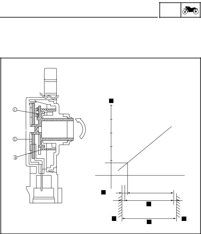
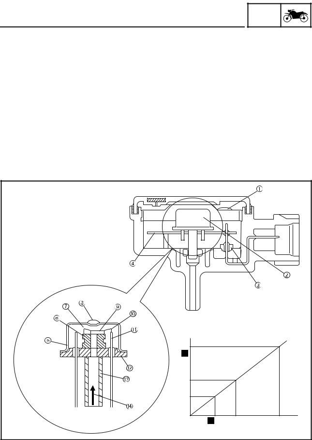
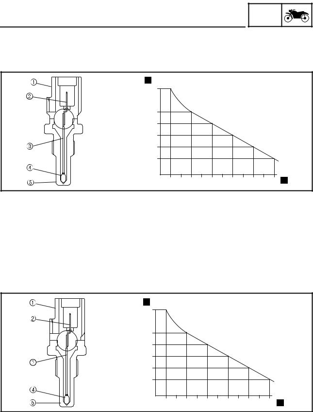
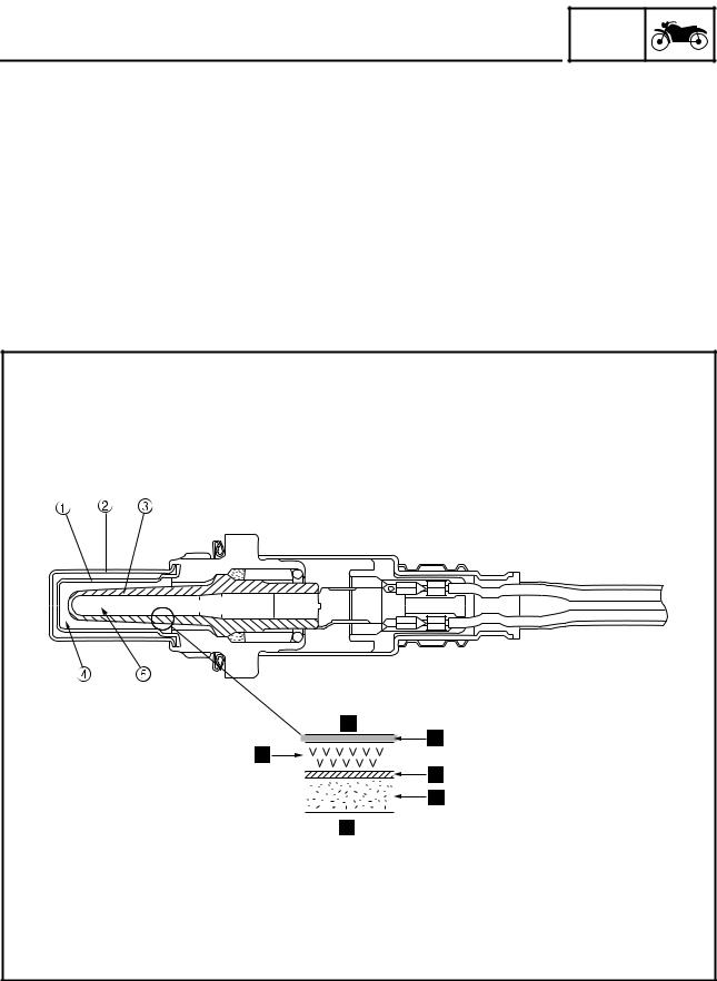
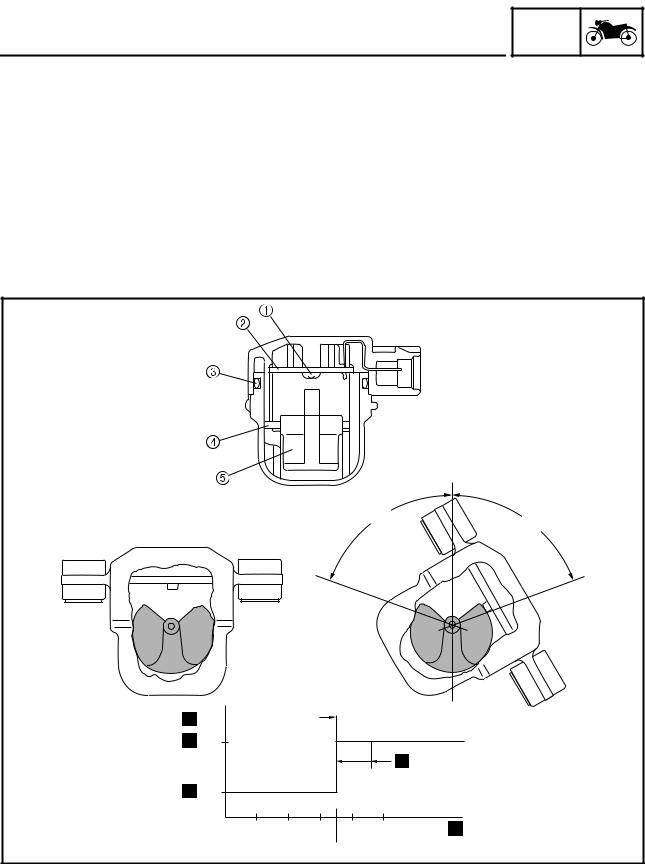
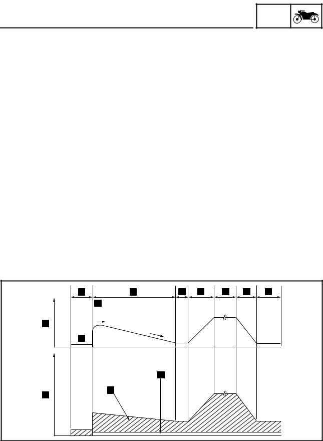
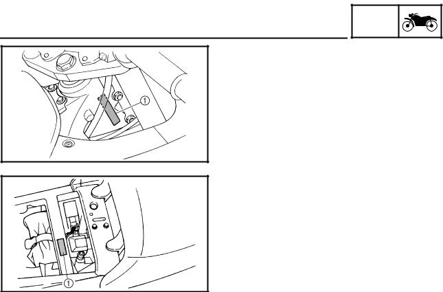
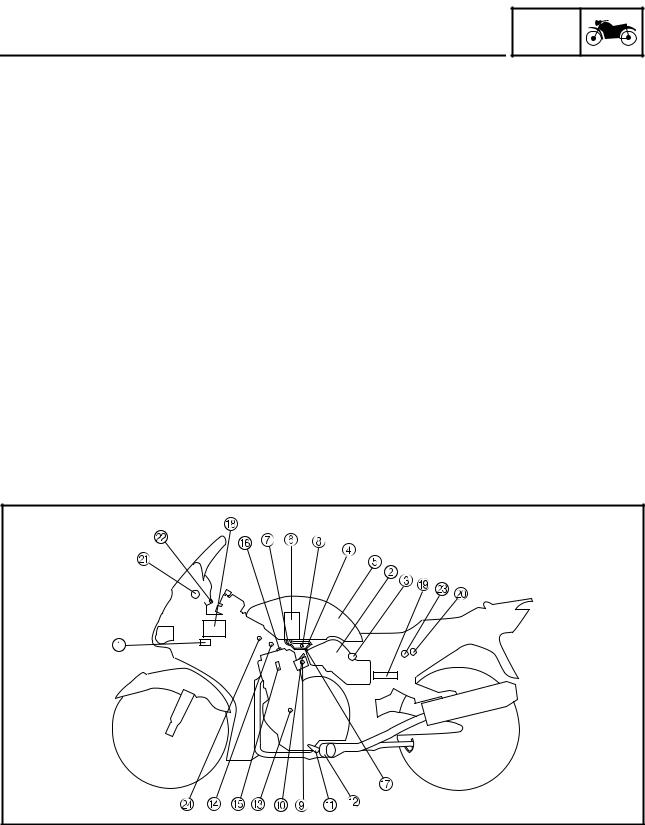
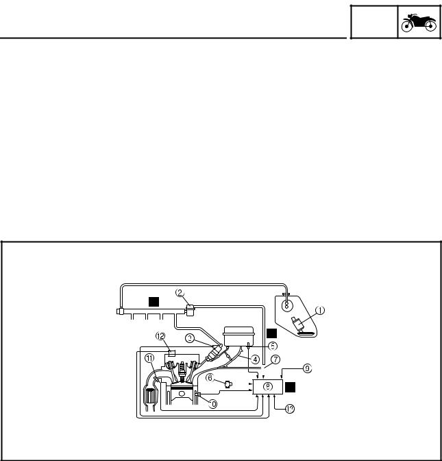
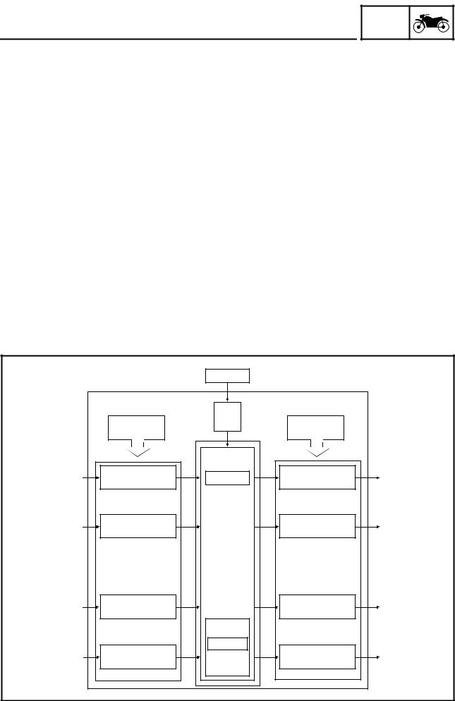
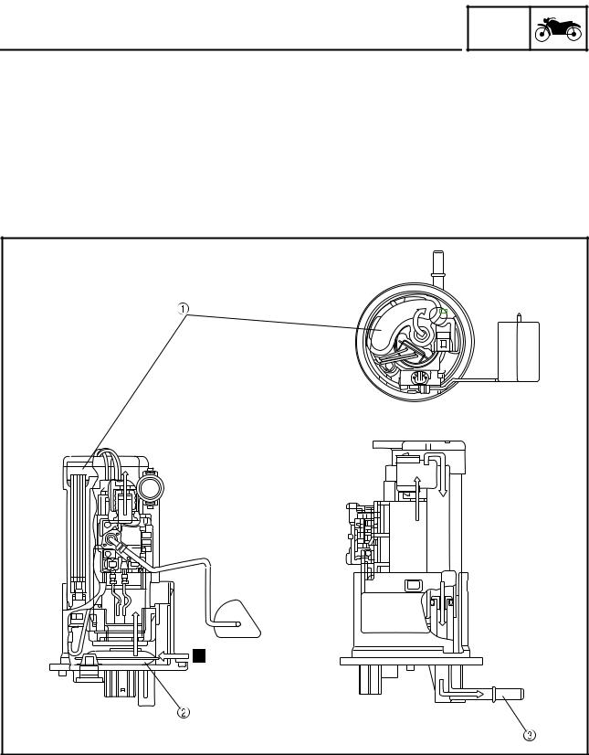
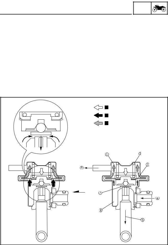
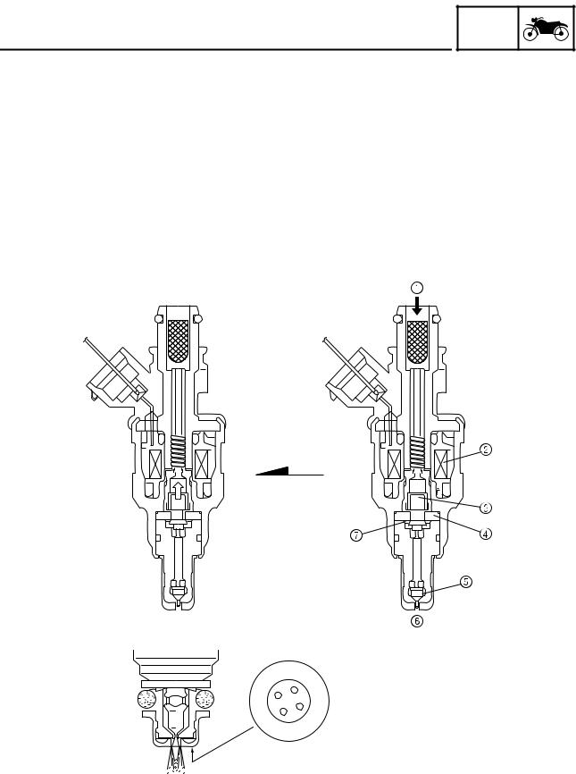
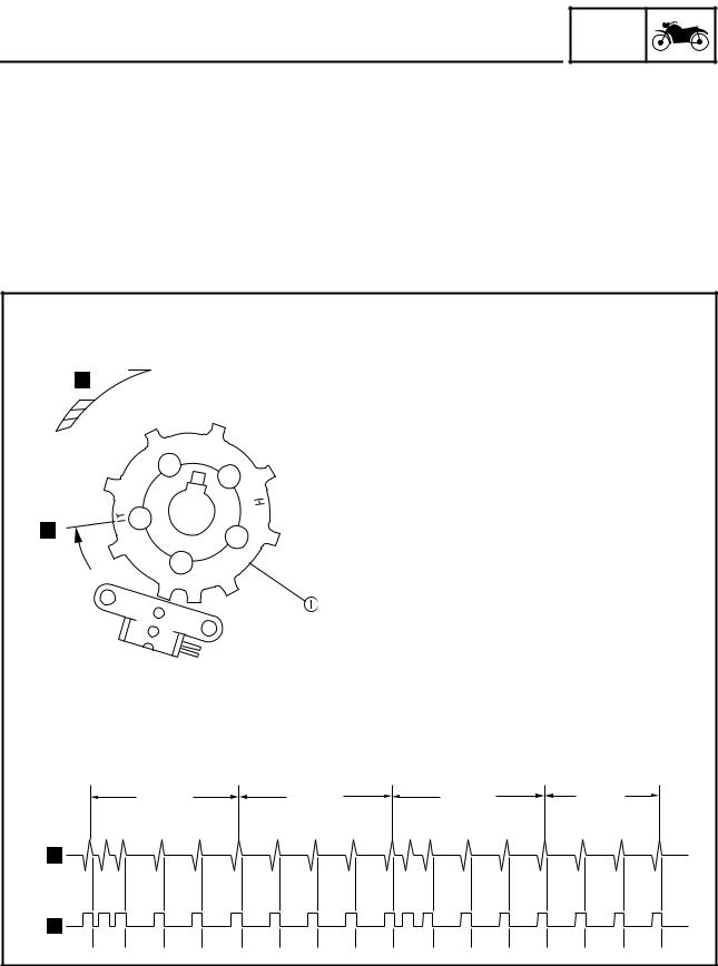
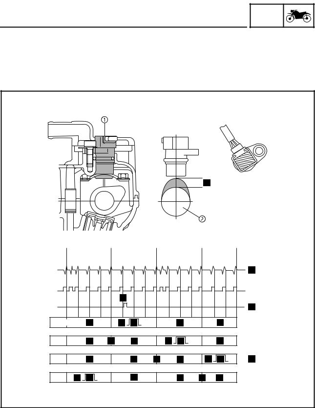
NOTE: A NOTE provides key information to make procedures easier or clearer. HOW TO USE THIS MANUAL This manual is intended as a handy, easy-to-read reference book for the mechanic. Comprehensive explanations of all installation, removal, disassembly, assembly, repair and check procedures are laid out with the individual steps in sequential order. 1 The manual is divided into chapters. An abbreviation and symbol in the upper right corner of each page indicate the current chapter. Refer to “SYMBOLS”. 2 Each chapter is divided into sections. The current section title is shown at the top of each page, except in chapter 3 (“PERIODIC CHECKS AND ADJUSTMENTS”), where the sub-section title(s) appears. 3 Sub-section titles appear in smaller print than the section title. 4 To help identify parts and clarify procedure steps, there are exploded diagrams at the start of each removal and disassembly section. 5 Numbers are given in the order of the jobs in the exploded diagram. A circled number indicates a disassembly step. 6 Symbols indicate parts to be lubricated or replaced. Refer to “SYMBOLS”. 7 A job instruction chart accompanies the exploded diagram, providing the order of jobs, names of parts, notes in jobs, etc. 8 Jobs requiring more information (such as special tools and technical data) are described sequentially. The following symbols are not relevant to every vehicle. Symbols 1 to 9 indicate the subject of each chapter. 1 General information 3 Periodic checks and adjustments 6 Cooling system 7 Fuel injection system 8 Electrical system Symbols 0 to G indicate the following. 0 Serviceable with engine mounted A Filling fluid D Tightening torque E Wear limit, clearance G Electrical data Symbols H to M in the exploded diagrams indicate the types of lubricants and lubrication points. J Molybdenum disulfide oil K Wheel bearing grease L Lithium soap base grease M Molybdenum disulfide grease Symbols N to O in the exploded diagrams indicate the following. N Apply locking agent (LOCTITE ® ) O Replace the part TABLE OF CONTENTSPERIODIC CHECKS AND FUEL INJECTION SYSTEM GENERAL INFORMATIONVEHICLE IDENTIFICATION NUMBER . FUEL INJECTION SYSTEM. THREE-WAY CATALYTIC CONVERTER SYSTEM. AIR INDUCTION SYSTEM. PREPARATION FOR REMOVAL AND DISASSEMBLY. GASKETS, OIL SEALS AND O-RINGS . LOCK WASHERS/PLATES AND COTTER PINS . BEARINGS AND OIL SEALS . CHECKING THE CONNECTIONS. MOTORCYCLE IDENTIFICATION INFO VEHICLE IDENTIFICATION NUMBER The vehicle identification number 1 is stamped into the right side of the steering head pipe. The model code label 1 is affixed to the frame. This information will be needed to order spare parts. FEATURESThe main function of a fuel supply system is to provide fuel to the combustion chamber at the optimum air-fuel ratio in accordance with the engine operating conditions and the atmospheric temperature. In the conventional carburetor system, the air-fuel ratio of the mixture that is supplied to the combustion chamber is created by the volume of the intake air and the fuel that is metered by the jet that is used in the respective chamber. Despite the same volume of intake air, the fuel volume requirement varies by the engine operating conditions, such as acceleration, deceleration, or operating under a heavy load. Carburetors that meter the fuel through the use of jets have been provided with various auxiliary devices, so that an optimum air-fuel ratio can be achieved to accommodate the constant changes in the operating conditions of the engine. As the requirements for the engine to deliver more performance and cleaner exhaust gases increase, it becomes necessary to control the air-fuel ratio in a more precise and finely tuned manner. To accommodate this need, this model has adopted an electronically controlled fuel injection (FI) system, in place of the conventional carburetor system. This system can achieve an optimum air-fuel ratio required by the engine at all times by using a microprocessor that regulates the fuel injection volume according to the engine operating conditions detected by various sensors. The adoption of the FI system has resulted in a highly precise fuel supply, improved engine response, better fuel economy, and reduced exhaust emissions. Furthermore, the air induction system (AI system) has been placed under computer control together with the FI system in order to realize cleaner exhaust gases. 1 Ignition coil 8 Intake air pressure L Engine trouble warn- 2 Air filter case F Cylinder identifica- 3 Intake temperature 9 Throttle position sensor M Lean angle cut-off 0 Fuel injector G Pressure regulator 4 Fuel delivery hose N Air cut-off valve B Catalytic converter C Crankshaft position J Atmospheric pressure 7 Fuel return hose D Coolant temperature K Fuel injection system FI SYSTEMThe fuel pump delivers fuel to the injector via the fuel filter. The pressure regulator maintains the fuel pressure that is applied to the injector at only 2.55 kg/cm 2 higher than the intake manifold pressure. Accordingly, when the energizing signal from the ECU energizes the injector, the fuel passage opens, causing the fuel to be injected into the intake manifold only during the time the passage remains open. Therefore, the longer the length of time the injector is energized (injection duration), the greater the volume of fuel that is supplied. Conversely, the shorter the length of time the injector is energized (injection duration), the lesser the volume of fuel that is supplied. The injection duration and the injection timing are controlled by the ECU. Signals that are input from the throttle position sensor, crankshaft position sensor, intake air pressure sensor, atmospheric pressure sensor, intake temperature sensor, coolant temperature sensor, and O 2 sensor enable the ECU to determine the injection duration. The injection timing is determined through the signals from the crankshaft position sensor and the cylinder identification sensor. As a result, the volume of fuel that is required by the engine can be supplied at all times in accordance with the driving conditions. Illustration is for reference only. #4 #3 #2 #1 6 Throttle position sen- 0 Coolant temperature 2 Pressure regulator 3 Fuel injector 7 Intake air pressure Ê Control system 4 Throttle body B Cylinder identification 5 Intake temperature 9 Atmospheric pressure C Crankshaft position Fuel control blockThe fuel control block consists of the following main components: Total FI system control Air volume control Fuel pressure detection Intake air pressure sensor Intake air pressure detection Atmospheric pressure sensor Atmospheric pressure detection Coolant temperature sensor Coolant temperature detection Intake temperature sensor Intake temperature detection Throttle position sensor Throttle angle detection Gas emission O 2 concentration detection Cylinder identification sensor Reference position detection Crankshaft position sensor Crankshaft position detection and engine Air Induction system, air cut valve Induction of secondary air An FI warning light is provided on meter panel. ECU (Electronic Control Unit) The ECU is mounted underneath the seat, below the toolbox. The main functions of the ECU are ignition control, fuel control, self-diagnosis, and load control. • ECU’s internal construction and functions The main components and functions of the ECU can be broadly divided into the following four items: A. Power supply circuit The power supply circuit obtains power from the battery (12 V) to supply the power (5 V) that is required for operating the ECU. B. Input interface circuits The input interface circuits convert the signals output by all the sensors into digital signals, which can be processed by the CPU, and input them into the CPU. C. CPU (Central Processing Unit) The CPU determines the condition of the sensors in accordance with the level of the signal that is output by the respective sensor. Then, the signals are temporarily stored on the RAM in the CPU. Based on those stored signals and the basic processing program on the ROM, the CPU calculates the fuel injection duration, injection timing, and ignition timing, and then sends control commands to the respective output interface circuits. D. Output interface circuits The output interface circuits convert the control signals output by the CPU into actuating signals for the respective actuators in order to actuate them. They also output commands to the indicator and relay output circuits as needed. Pickup coil signal Ignition output circuit (for identifying the Digital input circuit The ignition control function of the ECU controls the ignition timing and the duration of ignition energizing. The ignition timing control uses the signals from the throttle position sensor (to detect the angle of the throttle), and the crankshaft position sensor and speed sensor (to detect the speed of the engine). This control establishes an ignition timing that suits the operating condition of the engine through compensations made to the basic ignition timing control map. The ignition energizing duration control establishes the energizing duration to suit the operating conditions by calculating the energizing duration in accordance with the signal received from the crankshaft position sensor and the battery voltage. The fuel control function of the ECU controls the injection timing and injection duration. The injection timing control controls the injection timing during the starting of the engine and the injection timing during the normal operation of the engine, based on the signals received from the crankshaft position sensor and the cylinder identification sensor. The injection duration control determines the duration of injection based on the signals received from the atmospheric pressure sensors, temperature sensors, and the position sensors, to which compensations are made to suit various conditions such as the weather, atmospheric pressure, starting, acceleration, and deceleration. The ECU effects load control in the following manner: 1. Stopping the fuel pump and injectors when the motorcycle overturns The ECU turns OFF the fuel injection system relay when the lean angle cut-off switch is tripped. 2. Operating the headlight illumination relay On the model for Europe, the ECU causes the headlight relay 2 to output a constant ON signal, provided that the main switch is ON. On the model for Australia, the ECU controls the headlight relay 2 in accordance with the engine speed as required by the daytime illumination specification. 3. Operating the radiator fan motor in accordance with the coolant temperature The ECU controls the radiator fan motor relay ON/OFF in accordance with the coolant temperature. 4. Operating the AI system solenoid valve The ECU controls the energizing of the solenoid valve in accordance with the driving conditions. The ECU is equipped with a self-diagnosis function to ensure that the engine control system is operating normally. The ECU mode functions include a diagnosis mode in addition to the normal mode. • To check for any blown bulbs, this mode illuminates a warning light while the main switch is turned ON, and while the starter switch is being pressed. • If the starting disable warning is activated, this mode alerts the rider by blinking the warning light while the start switch is being pressed. • If a malfunction occurs in the system, this mode provides an appropriate substitute characteristic operation, and alerts the rider of the malfunction by illuminating a warning light. After the engine is stopped, this mode displays a fault code on the clock LCD. • In this mode, a diagnostic code is input into the ECU through the operation of the operating switch on the meter, and the ECU displays the values output by the sensors or actuates the actuators in accordance with the diagnostic code. Whether the system is operating normally can be checked by observing the illumination of the warning light, the values displayed on the meter, or the actuating state of the actuators. Fuel pumpThe fuel pump, which is mounted in the fuel tank, draws the fuel directly from the tank and pumps it to the injector. A filter that is provided in the fuel pump prevents any debris in the fuel tank from entering the fuel system downstream of the pump. The pump consists of a pump unit, electric motor, filter, and valves. The pump unit is a Wesco type rotary pump that is connected to the motor shaft. A relief valve is provided to prevent the fuel pressure from rising abnormally if the fuel hose becomes clogged. This valve opens when the fuel pressure at the discharge outlet reaches between 440 and 640 kpa, and returns the fuel to the fuel tank. 2 Fuel inlet strainer Pressure regulatorIt regulates the fuel pressure that is applied to the injectors that are provided in the cylinders in order to maintain a constant pressure difference with the pressure in the intake manifold. The fuel that is delivered by the fuel pump fills the fuel chamber through the fuel inlet of the regulator and exerts pressure on the diaphragm in the direction for opening the valve. A spring that is provided in the spring chamber exerts pressure on the diaphragm in the direction for closing the valve, in contrast to the pressure of the fuel. Thus, the valve cannot open unless the fuel pressure overcomes the spring force. An intake vacuum is applied to the spring chamber via a pipe. When the pressure of the fuel exceeds the sum of the intake vacuum and the spring force, the valve that is integrated with the diaphragm opens, allowing the fuel to return from the fuel outlet to the fuel tank, via the fuel return hose. As a result, because the intake vacuum fluctuates in accordance with the changes in the operating conditions in contrast to the constant volume of fuel supplied by the pump, the valve opening/closing pressure also changes to regulate the return fuel volume. Thus, the difference between the fuel pressure and the intake manifold pressure remains constant at a prescribed pressure. 1 Spring chamber È Spring pressure 8 Intake manifold vac- É Fuel pressure Ê Vacuum pressure Fuel injectorUpon receiving injection signals from the ECU, the fuel injector injects fuel. In the normal state, the core is pressed downward by the force of the spring, as illustrated. The needle that is integrated with the bottom of the core keeps the fuel passage closed. When the current flows to the coil in accordance with the signal from the ECU, the core is drawn upward, allowing the flange that is integrated with the needle to move to the spacer. Since the distance of the movement of the needle is thus kept constant, the opening area of the fuel passage also becomes constant. Because the pressure difference of the fuel to the intake manifold pressure is kept constant by the pressure regulator, the fuel volume varies in proportion to the length of time the coil is energized. The injector that has been recently adopted has a four-hole type injection orifice that enhances the atomization of fuel and improves combustion efficiency. Crankshaft position sensorThe crankshaft position sensor uses the signals of the pickup coil that is mounted on the right side of the crankshaft. When the rotation of the pickup rotor that is attached to the crankshaft causes the projections on the rotor to pass by the pickup coil, an electromotive force is generated in the coil. The voltage of this force is then input into the ECU, which calculates the position of the crankshaft and the speed of the engine. The ignition timing is then determined in accordance with the calculated data, in order to determine the corresponding injection timing. Based on the changes in the time intervals of the signals generated by the pickup coil, the ECU calculates the ignition timing advance to suit the operating conditions. The injection timing is also advanced in accordance with the ignition timing in order to supply fuel to the engine at an optimal timing. È Direction of rotation É #1 cylinder compression stroke, 5° BTDC Ê Pickup signal Cylinder identification sensorThe cylinder identification sensor is mounted on the exhaust head cover of the #4 cylinder. When the exhaust cam of the #4 cylinder rotates and the lift of the cam passes by the sensor, the sensor generates a signal and sends it to the ECU. Based on this signal and the signal from the crankshaft position sensor, the ECU then actuates the injector of the cylinder that is currently in order to supply fuel. #1 1 Cylinder identification Ë Cylinder firing order É Crankshaft position Ì #4 cam lobe onto Ê Cylinder identification Throttle position sensorThe throttle position sensor measures the intake air volume by detecting the position of the throttle valve. It detects the mechanical angle of the throttle valve through the positional relationship between the moving contact that moves in unison with the throttle shaft and the resistor board. In actual operation, the ECU supplies 5 V power to both ends of the resistor board and the voltage that is output by the throttle position sensor is used to determine the angle of the throttle valve. 1 Moving contact È Output voltage 2 Resistor board É Idling output position Ê Mechanical stopper Ë Mechanical stopper Ì Effective electrical angle Í Sensor operating angle Intake air pressure sensor and atmospheric pressure sensor• Intake air pressure sensor The intake air pressure sensor is used for measuring the intake air volume. The intake air volume of every intake stroke is proportionate to the intake air pressure. Therefore, the intake air volume can be measured by measuring the intake air pressure. The intake air pressure sensor converts the measured intake air pressure into electrical signals and sends those signals to the ECU. When the intake air pressure is introduced into the sensor unit, which contains a vacuum chamber on one side of the silicon diaphragm, the silicon chip that is mounted on the silicon diaphragm converts the intake air pressure into electrical signals. Then, an integrated circuit (IC) amplifies and adjusts the signals and makes temperature compensations, in order to generate electrical signals that are proportionate to the pressure. • Atmospheric pressure sensor The atmospheric pressure sensor is used for making compensations to the changes in the air density caused by the changes in the atmospheric pressure (particularly at high altitudes). The operating principle and function of the atmospheric pressure sensor are the same as those of the aforementioned intake air pressure sensor. 6 Silicon diaphragm È Output voltage 7 Vacuum chamber É Input pressure 3 Through condenser C Pressure induction pipe D Atmospheric pressure, intake air pressure Coolant temperature sensor The signals from the coolant temperature sensor are used primarily for making fuel volume compensations during starting and warm-up. The coolant temperature sensor converts the temperature of the coolant into electrical signals and sends them to the ECU. È Resistance kΩ É Temperature °C Intake temperature sensor The intake temperature sensor corrects the deviation of the air-fuel mixture that is associated with the changes in the intake air density, which are created by the changes in the intake air temperature that occur due to atmospheric temperatures. This sensor uses a semi-conductor thermistor that has a large resistance at low temperatures and a small resistance at high temperatures. The thermistor converts the temperature-dependent changes in resistance into electrical resistance values, which are then input into the ECU. È Resistance kΩ É Temperature °C O 2 sensorThe O 2 sensor has been adopted to enable the catalyst to function at a high degree of efficiency by maintaining the air-fuel mixture near the stoichiometric ratio (14.7:1). This sensor, which is a zirconia type, utilizes the oxygen ion conductivity of the solid electrolyte for detecting the oxygen concentration levels. In actual operation, a zirconia tube made of solid electrolyte is exposed in the exhaust gas, so that the exterior of the zirconia tube is in contact with the exhaust gas and the interior is in contact with the atmosphere whose oxygen concentration level is known. When a difference in the oxygen concentration level is created between the outside and the inside of the zirconia tube, the oxygen ion passes through the zirconia element and generates an electromotive force. The electromotive force increases when the oxygen concentration level is low (rich air-fuel ratio) and the electromotive force decreases when the oxygen concentration level is high (lean air-fuel ratio). As electromotive force is generated in accordance with the concentration of the exhaust gas, the resultant voltage is input into the ECU in order to correct the duration of the injection of fuel. Ë Outer electrode É Inner electrode Ì Porous ceramic layer 3 Zirconia tube Ê Zirconia element Lean angle cut-off switchThe lean angle cut-off switch stops the supply of fuel to the engine in case the motorcycle overturns. When the motorcycle is in the normal state, the cut-off switch outputs a constant voltage of approximately 1.0 V (low level). When the motorcycle tilts, the float in the switch tilts in proportion to the tilt of the motorcycle. However, the voltage output to the ECU remains unchanged at the low level. When the tilt of the motorcycle exceeds 70 degrees (according to the tilt of the float), the signal from the sensor increases to approximately 4.0 V (high level). When the ECU receives the high-level voltage, it determines that the motorcycle has overturned, and stops the delivery of fuel to the engine by turning OFF the fuel injection system relay that powers the fuel pump and the injectors. Once the cut-off switch is tripped, the ECU maintains this state; therefore, even if the motorcycle has recovered its upright position, this state will not be canceled unless the main switch is turned OFF, and then turned back ON. È Output voltage Ë Cut-off switch tilt angle Ì Fuel injection system FUEL INJECTION SYSTEM Operation and controlThe fuel injection timing, injection duration, ignition timing, and the coil energizing duration are controlled by the ECU. To determine the basic injection timing, the ECU calculates the intake air volume through the signals from the intake air pressure sensor, throttle position sensor, cylinder identification sensor, and crankshaft position sensor. Furthermore, the ECU calculates the final injection timing by adding the following compensations to the aforementioned basic injection duration: those obtained from the state of acceleration, as well as those based on the signals from various sensors such as the coolant temperature, intake temperature, atmospheric, and exhaust pipe oxygen concentration level. At the same time, the ECU assesses the crankshaft position through the signals from the cylinder identification sensor and the crankshaft position sensor. Then, when the ECU determines that it is time to inject fuel, it sends an injection command to the injectors. Furthermore, the ECU also controls the length of time the coil is energized by calculating the ignition timing and the coil energizing duration based on the signals from these sensors. Determining the basic injection duration The intake air volume determines the basic injection duration. In order to operate the engine in an optimal condition, it is necessary to supply fuel at an air-fuel ratio that corresponds appropriately to the volume of intake air that is constantly changing, and to ignite it an appropriate timing. The ECU controls the basic injection duration based on the intake air volume and engine speed data. Detection of intake air volume The intake air volume is detected primarily through the signals from the throttle position sensor and the intake air pressure sensor. The intake air volume is determined in accordance with the signals from the atmospheric pressure sensor, intake temperature sensor, and the engine speed data. Источник |






 За основу Yamaha FJR1300 был взят рядный 4-цилиндровый инжекторный двигатель жидкостного охлаждения, объемом 1298 куб. см., выдающий 143 л.с. мощности и 134 Нм крутящего момента. В 2013 году были оптимизированы катализаторы и максимальная мощность повысилась до 146 л.с., а крутящий момент — до 138 нм. Максимальные характеристики мотора достигаются уже на 7000-8000 об/мин. Несмотря на выдающиеся технические характеристики, официальный расход топлива заявлен на отметке 6,2 л / 100 км.

 WARNING Failure to follow WARNING instructions could result in severe injury or death to
 CAUTION:
 A CAUTION indicates special precautions that must be taken to avoid damage to the motorcycle.






 180˚
180˚ 
 180˚
180˚ 
 180˚
180˚ 
 180˚
180˚

